Knowledge
Security is not only the future value of YSMETER, but also the core interest that YSMETER brings to customers
Sep. 09,2026
Share:
In oil-handling systems, the term oil control valve can refer to several different valve types. The right choice depends on what the valve must do in the process: regulate flow, maintain pressure, direct oil between lines, or provide dependable shutoff.
YSmeter supports industrial fluid-control projects, with a control valve range that provides a practical starting point for application review.
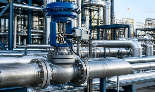
Not all oils behave the same way. Hydraulic oil, lubricating oil, fuel oil, thermal oil, and waste oil can differ significantly in viscosity, temperature, cleanliness, and chemical composition.
Viscosity is particularly important. A valve sized for a low-viscosity fluid may not deliver the expected flow response when handling a heavier oil. Contaminants, suspended particles, or degraded oil can also affect seat wear, blockage risk, and maintenance intervals.
Before selecting a valve, confirm:
Oil type, viscosity, and temperature range
Normal and maximum flow rate
Inlet, outlet, and differential pressure
Presence of solids, water, wax, or other contaminants
Required valve function: control, isolation, pressure regulation, or diversion
“Oil control valve” describes an application, not one fixed valve construction. A control valve may be selected where stable flow or pressure adjustment is required. A ball valve may be appropriate for fast, reliable isolation. Globe-style designs may be reviewed where more precise throttling is needed.
The selection should also consider whether the valve will remain mostly open or closed, cycle frequently, or operate continuously at intermediate positions. Using an isolation valve for sustained throttling, for example, can lead to unstable control or accelerated wear.
For automated systems, the actuator must provide sufficient torque or thrust under the actual differential pressure. The project should also define the required control signal, feedback position, and fail-safe action if air or power is lost. The pneumatic control valve guide offers a useful reference for understanding pneumatic actuation and control requirements.
The wetted materials and sealing system must be compatible with the specific oil and operating temperature. This review should cover the valve body, trim or disc, seals, packing, and any soft components exposed to the medium.
Installation conditions matter as well. Ensure there is access for actuator maintenance, filter cleaning, inspection, and valve removal. If the oil contains contamination, placing suitable filtration upstream and allowing space for maintenance can help protect the valve and improve service reliability.
Provide the following information when requesting a technical review:
| Information | Why it matters |
|---|---|
| Oil type and viscosity | Helps assess flow behavior and material compatibility. |
| Flow, pressure, and temperature | Supports valve sizing and operating-range review. |
| Required function | Determines whether the valve is for control, shutoff, diversion, or pressure duty. |
| Pipe connection and line size | Confirms installation compatibility. |
| Actuation and control requirements | Defines the actuator, control signal, and fail position. |
For wider system planning, review YSmeter’s industrial valve portfolio. Where oil properties or control requirements need closer assessment, contact the engineering team with the available process data before final selection.
More News